


You press the window switch, hear nothing, and try again with a little more force, as if the door might suddenly change its mind. Sometimes there's only silence. Other times the motor groans behind the trim while the glass stays fixed. Before you order a motor or regulator, treat the fault as a circuit problem. Power window motor wiring follows a simple logic even when the harness, modules, connectors, and wire colors vary by vehicle.
The reliable approach is to work from the fuse and switch toward the motor, checking each point under the conditions in which the window should operate. That prevents a new part from becoming an expensive substitute for a loose ground, damaged door-jamb wire, or oxidized connector.
Table of Contents
- When Your Window Stops Cooperating
- How Power Window Motor Wiring Actually Works
- Wire Colors and Pinouts Across Common Makes
- Wiring a Replacement Motor Step by Step
- Diagnosing Power Window Wiring With a Multimeter
- Why Grounds and Connectors Beat a New Motor
- Field-Tested Tips and a Quick Wiring Checklist
When Your Window Stops Cooperating
A dead window usually belongs to one of four fault families: switch failure, regulator damage, motor failure, or wiring and ground trouble. The symptom helps narrow the field, but it doesn't identify the failed part by itself. A silent switch may have no feed, a broken internal contact, or a disconnected motor circuit. A clicking or straining sound may indicate a jammed regulator rather than a bad motor.
Start with the easy checks before removing the door panel. Confirm whether the other windows work, listen for a click or motor noise, inspect the fuse or circuit breaker, and try the switch from both the driver's master panel and the affected door if the vehicle provides both controls. These checks tell you whether the problem is isolated to one door or shared across the control circuit.
Use a diagnostic ladder
Work through the fault in this order:
- Power protection: Check the fuse or breaker and confirm that the window circuit receives battery voltage.
- Switch command: Test whether the switch sends voltage to the motor circuit in both directions.
- Door harness: Flex the rubber door boot while testing, then inspect the jamb connector and ground path.
- Motor and regulator: If the motor receives the correct command but the glass doesn't move, separate a seized motor from a mechanical regulator fault.
Practical rule: Don't remove the regulator until you know whether the motor is receiving a command. Mechanical access takes time, electrical testing often takes minutes.
The wiring belongs near the bottom of this ladder because it's easy to blame after the door card is already off. Yet the first checks are faster and can prevent unnecessary parts replacement. A fuse check, switch test, and motor-connector voltage test will usually tell you whether you're dealing with control, delivery, or mechanical movement.
The rest of the job becomes much clearer once you understand the circuit itself. Wire colors, connector shapes, and comfort modules are vehicle-specific details layered over a basic polarity-reversal design.
How Power Window Motor Wiring Actually Works
A power window that moves up but not down usually has one wiring question behind it: can the circuit reverse polarity at the motor? Most conventional systems use a permanent-magnet DC motor with two terminals. Apply voltage with one polarity and the motor turns one direction. Reverse the polarity and it turns the other, raising or lowering the glass depending on the switch command.
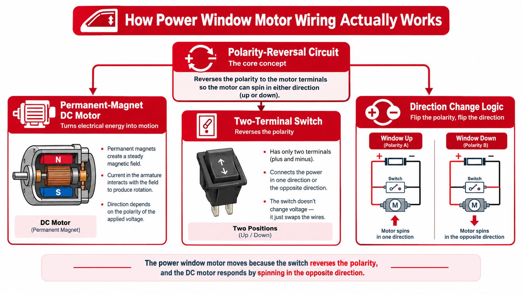
A fused or breaker-protected feed supplies the control circuit. The master switch and door switch select direction, then the motor receives the reversed polarity through the switch assembly or a control module. In a basic two-wire arrangement, the switching circuit provides both sides of the motor circuit. The motor therefore does not need a separate ground terminal.
Why wire size and protection matter
Window motors draw far more current than small control devices. One wiring guide commonly specifies 20A to 25A protection for standard window motor circuits, 14 AWG for switch-to-motor runs, and a 12 AWG main feed from the battery or fuse block to the cabin. Its recommendations are outlined in this power window wiring safety guide.
A separate technical reference gives normal motor draw at about 5A to 10A, with example full-load and stall values around 10A and 15A. The figures appear in this power window motor wiring reference. A frozen or binding regulator can hold the motor at high load, so the fuse or breaker must allow normal movement while limiting heat and harness damage during a stall.
Some vehicles use a circuit breaker or auto-reset breaker instead of a conventional fuse. It may restore power after a temporary overload, but a jammed regulator can produce a repeating cycle: brief operation, cutout, reset, and another cutout. The breaker limits electrical damage. It does not repair the mechanical fault.
The simple circuit has modern exceptions
Older vehicles often placed more wires at the switch because the switch handled polarity reversal directly. A technical history of Mercedes-Benz systems reports that, before 1990, front switches used five wires for power, ground, two motor-direction paths, and illumination. That history identifies the 124 and 129 chassis as the first Mercedes models in that source to use an electronic window control unit in 1990, reducing the switch connection to three wires. See the Mercedes power window wiring history for that change.
Modern vehicles may send low-current switch signals to a body or comfort module. The module then drives the motor through relays or solid-state outputs. Some systems also add a third motor-related wire for position, speed, or pinch-protection data.
Treat every connector as a variation of the same circuit problem: identify the two terminals that change polarity, then establish where the feed and return paths originate. Wire color can help organize the harness. The vehicle wiring color code guide is useful for orientation, but a vehicle-specific diagram and meter test should decide which terminal does what.
Wire Colors and Pinouts Across Common Makes
Wire colors are useful for orientation, not proof. Manufacturers change colors across model years, trim packages, market versions, and module layouts. A wire that carries motor direction on one vehicle may carry a switch signal on another, so never cut a harness solely because two colors look familiar.
The table below is a starting map for common patterns. It isn't a substitute for a wiring diagram or a voltage test at the connector.
Power Window Motor Wire Color Reference by Manufacturer
| Make | Direction 1 Wire | Direction 2 Wire | Power Feed | Notes |
|---|---|---|---|---|
| Ford | Light blue or violet | Tan or white | Model-dependent | Colors can change by year and trim; verify at the motor connector. |
| GM | Dark blue | Brown | Pink or black | Door harness layouts vary, especially when a module controls the window. |
| Toyota | Red or black combinations | Green or yellow combinations | Model-dependent | Auto-up and pinch-protection systems may add control wiring. |
| Honda | Red or black combinations | Green or yellow combinations | Model-dependent | Confirm whether the switch is direct control or module-based. |
| BMW | Vehicle-specific | Vehicle-specific | Often module-controlled | Older systems may route through a comfort module and use thinner control wiring. |
| Mercedes-Benz | Vehicle-specific | Vehicle-specific | Often module-controlled | Earlier and later designs can differ substantially in switch wire count. |
| Volkswagen | Vehicle-specific | Vehicle-specific | Often module-controlled | Connector pin numbers are more dependable than color alone. |
Ford commonly uses a two-wire motor arrangement with light blue or violet associated with one direction and tan or white with the other, depending on the application. GM door harnesses frequently show dark blue and brown motor-direction wires, with pink or black appearing as a main feed in some layouts. Those patterns can help you find the likely motor pair, but they don't tell you whether the switch or module is supplying voltage.
Toyota and Honda often use red or black combinations alongside green or yellow direction wires. Vehicles with automatic window functions may add wiring for pinch protection, position sensing, or module communication. That extra wire shouldn't be treated as a third motor-power lead without checking the diagram.
European cars deserve more caution. Older BMW, Mercedes-Benz, and Volkswagen designs may use thinner wires for switch or module signals and place the actual motor control in a comfort module. A direct battery test on the wrong terminal can damage an electronic driver, so identify the motor connector before applying power.
Don't trust a color until it passes two tests: trace it to the correct connector, then measure what it does while the switch is operated.
Wiring a Replacement Motor Step by Step
Prepare the door before touching the motor. Disconnect the negative battery cable, protect your hands with insulated gloves, and confirm that the replacement has the correct mounting footprint, gear arrangement, connector, and regulator compatibility. A motor that bolts in but uses the wrong gear or connector can create a second fault during installation.
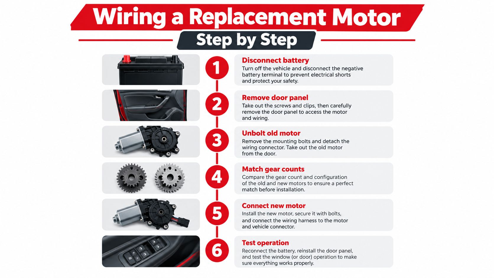
Photograph the harness routing and connector orientation before unbolting anything. If you need a refresher on trim removal, follow this guide to removing a car door panel. Keep the glass supported, loosen the regulator-to-glass clamps as required by the vehicle, and position the glass so you have clearance without allowing it to drop.
Make the connection mechanically sound
If the replacement motor uses the original plug, transfer the connector only when the terminal arrangement matches. If it needs a pigtail adapter, compare the harness-side wires with the original motor before joining anything. Don't assume the replacement lead colors match the vehicle harness colors.
Use a proper crimp tool with sealed butt connectors, or solder the joint and cover it with adhesive-lined heat shrink. Twisting wires together and wrapping them in electrical tape may get a test result, but vibration, moisture, and the motor's current load make it a poor permanent repair.
- Match the motor pair: Identify the two wires that reverse polarity at the original connector.
- Join the adapter: Make each connection mechanically secure, then insulate it against moisture.
- Protect the route: Retape the harness along its factory path, away from the regulator's scissor arms, cables, and gears.
- Restore the connector: Lock the plug fully and check that no terminal has backed out of the housing.
- Test before trim: Reconnect the battery and test upward and downward movement with the door panel still removed.
Place the video later in the process, after the wiring has been matched and the motor is secured:
The window should move smoothly in both directions without harness contact or abnormal grinding. If the vehicle has auto-up, confirm that its reversal or pinch-protection behavior works before reinstalling the panel. Keep hands clear of the glass path, and don't leave the motor running with the regulator disconnected. A spinning motor without its intended mechanical load can damage the gear mechanism or create an unsafe loose part.
Diagnosing Power Window Wiring With a Multimeter
A window that stops halfway, works from one switch but not another, or moves only after you slam the door needs a circuit test before a replacement motor. Set the multimeter to DC voltage, confirm battery voltage and circuit protection, then follow the feed toward the motor. This power window motor test guide covers access to the motor connector, voltage checks there, and controlled direct-power testing.
For an analog two-wire motor, disconnect the motor before measuring across its two terminals. Operate the window switch in both directions. The meter should show approximately +12 volts or -12 volts, with the sign changing when the switch reverses polarity. That change shows the switch and wiring are commanding the motor. It does not prove the circuit can carry motor current under load.
Use each reading as a gate
| Test Point | Meter Setting | Expected Reading |
|---|---|---|
| Battery or main feed | DC volts | Battery voltage with the circuit available |
| Fuse or breaker feed | DC volts | Feed voltage present on the powered side |
| Switch output | DC volts | Voltage changes with the up and down command |
| Motor connector, unplugged | DC volts | Approximately +12 volts in one direction and -12 volts in the other |
| Motor terminals, unplugged | Resistance | A finite resistance reading, not an open circuit |
| Motor power and ground under load | DC volts | Minimal loss between supply and motor |
| Ground side under load | DC volts | Above 0.2 volts indicates a poor ground or corrosion concern |
Keep the motor unplugged for the polarity check. Its low internal resistance can pull the reading down and hide a switch or harness problem. Measuring only at the battery creates the same false confidence. The motor connector is the deciding test point because that is where the circuit must deliver usable power.
Check the circuit under load before condemning a component. A wiring benchmark places critical-circuit voltage drop at or below 3%, and a ground-side reading above 0.2 volts indicates a poor ground or corrosion concern. Compare battery voltage with the voltage reaching the motor while the switch is actuated. If the battery shows 12.6 volts but the motor receives only 9.5 volts, inspect for undersized wire, damaged conductors, or corroded connections. The automotive voltage-drop testing guide explains this measurement method.
A polarity change with low voltage points to resistance in the feed, ground, switch, connector, or door-jamb harness. Correct voltage and polarity shift the investigation to the motor and regulator. If the motor runs during a controlled direct-power test but not from the switch, trace the switch, harness, ground, and module path rather than buying another motor. Keep the regulator's mechanical load in mind, because binding can make a sound circuit appear weak.
Why Grounds and Connectors Beat a New Motor
A new motor won't repair a broken door-jamb conductor. It won't remove oxidation from a switch connector or restore tension to a terminal that has spread inside its housing. On older vehicles, the harness repeatedly flexes through the rubber boot, while moisture works its way into connectors and ground points.
Clean the accessible connector halves with electrical contact cleaner and inspect every terminal for green corrosion, discoloration, looseness, or backing out. Check the body-side and door-side connections, then inspect the ground attachment for rust, paint, or a loose fastener. A clean continuity reading is helpful, but a loaded voltage-drop test is more revealing because a weak connection can pass a low-current meter test and fail when the motor demands current.
A motor replacement is a conclusion, not a diagnostic method.
A high-resistance splice can make the window sluggish, intermittent, or completely dead. The regulator may also bind, increasing motor load and exposing a weak connection that was already present. Cleaning and securing the ground path before ordering parts often resolves the fault without disturbing the regulator.
The economical sequence is simple: spend the diagnostic time first, then buy the component the measurements identify. If the motor receives reversed voltage under load and still doesn't turn, replacement is justified. If voltage collapses before it reaches the motor, repair the wiring instead.
Field-Tested Tips and a Quick Wiring Checklist
Use this sequence as a glove-box checklist. Each line is a gate. A “no” answer sends you back to the previous electrical point rather than forward to a guessed part.
- Confirm the symptom: Is the window silent, clicking, slow, or mechanically jammed?
- Inspect protection: Is the fuse or breaker intact and receiving power?
- Test the switch: Does its output change when you select up and down?
- Check the connector: Does the motor plug receive reversed polarity?
- Verify the ground: Does the door-jamb and body ground hold voltage under load?
- Inspect terminals: Are pins clean, tight, straight, and fully seated?
- Test the motor safely: Does a fused jumper operate it with the regulator attached?
- Repair the harness: Are joins crimped or soldered and sealed with heat shrink?
- Replace only confirmed parts: Has wiring passed before you install a motor?
- Cycle the window: Does it move smoothly through three complete cycles after reassembly?
Four habits prevent repeat failures. Label connectors with painter's tape before disassembly. Never run a window motor without the regulator attached. Use dielectric grease where appropriate after cleaning and securing the terminals, and keep a fused jumper lead for a controlled direct-power test.
For replacement regulators, motors, and related door hardware, T1A Auto offers vehicle-specific aftermarket parts and fitment-focused product information that can help match the component to the application. Use the wiring tests first, then choose the replacement that matches the confirmed mechanical or electrical fault.
