


You're sitting in the driver's seat with the toad already hitched, the pad is tight, and the picture on the monitor is either late, washed out, or aimed at the sky. A rear view camera RV setup only earns its keep when the image is sharp, powered cleanly, and pointed at the ground you are about to roll over. Treat it as a measured visibility aid. Test coverage, voltage, and failures in rain and with the trailer on, instead of trusting a plug-and-play promise.
Table of Contents
- Rear View Camera Types and Which One Your RV Needs
- Power Sources and Cable Sizing for Long RV Runs
- How to Mount the Camera and Route the Cable
- How to Wire the Camera and Connect the Monitor
- Aiming and Testing Coverage on a Large RV
- Why a Camera Cannot Replace Mirrors or a Spotter
- Troubleshoot Faults Before You Replace the Camera
Rear View Camera Types and Which One Your RV Needs
Say you are backing a Class C into a campsite with a tow car still hitched. The mirrors show the coach sides and a slice of the campsite road. They miss the strip of gravel right behind the tow car, which is exactly where a picnic table, a sewer cap, or a child can sit. That gap is why the camera type has to match the rig, not the box art.
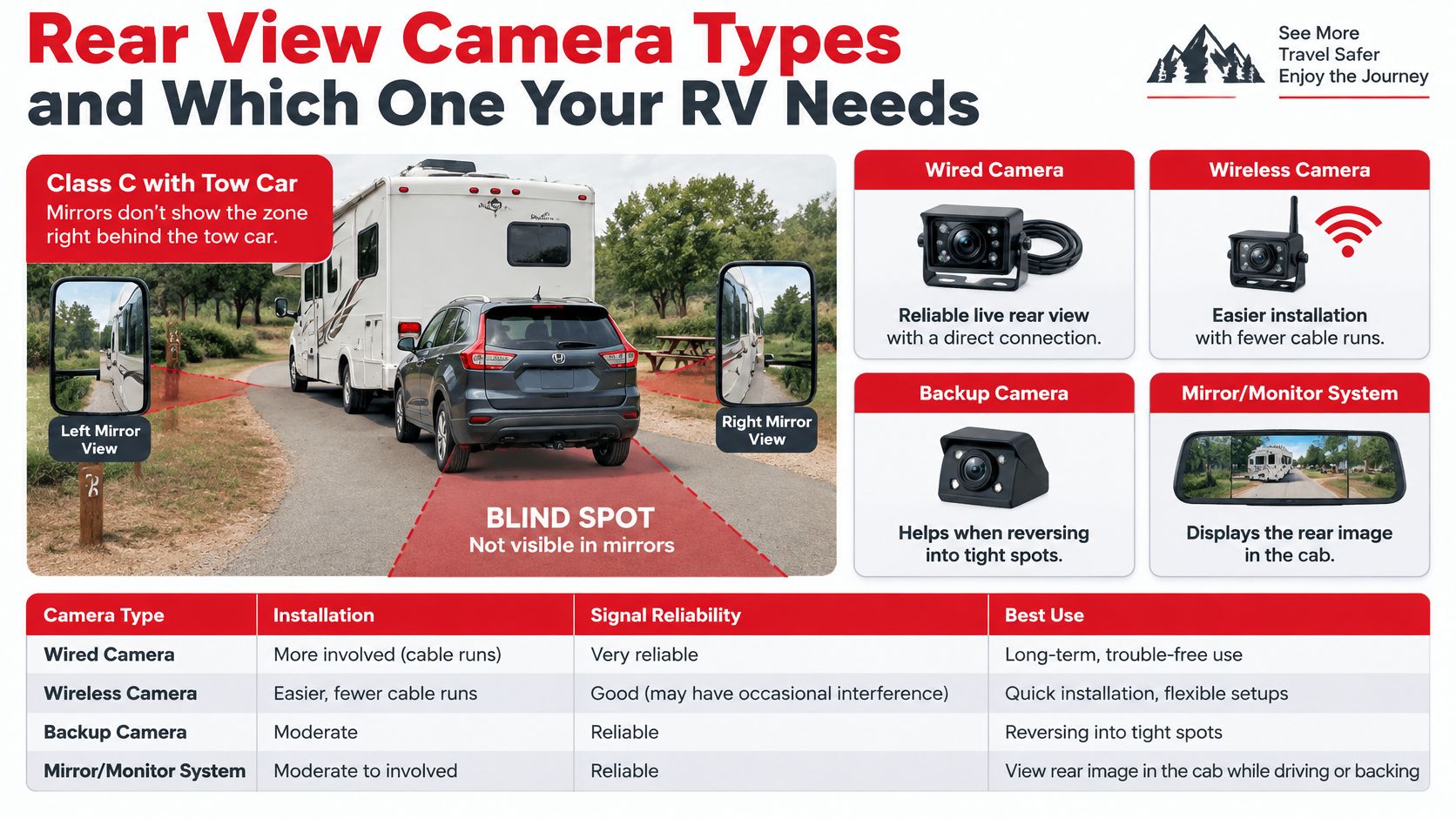
| Camera type | Best for | Signal and delay | Install effort |
|---|---|---|---|
| Wired backup camera | Motorhomes and travel trailers with a clear cable route | Direct feed, lowest delay | Moderate to high, cable runs through frame and bulkhead |
| Wireless digital backup camera | Fifth wheels and hitch-mounted setups where wiring is impractical | Digital link, possible dropouts or lag in metal-heavy rigs | Low to moderate, still needs 12V power at the camera |
| Side-view camera | Coach sides, slide-outs and awning zones | Wired or wireless, usually shown in split view | Moderate, mounted to body panel |
| Multi-camera surround system | Long coaches and tow combinations | Usually wired to a control unit | High, multiple cables and alignment |
A wired backup camera is the one I would start with on a motorhome or travel trailer that already has a path from the tail to the cab. The picture stays put at highway speed, and you are not hunting a pairing button when you need reverse. A wireless digital camera saves a long pull on a fifth wheel or a camera bolted to the hitch of a toad. Metal skin, inverters, and a dense campground can still drop the link, so pair it in the driveway and again with the generator running before you commit.
Side cameras cover slide-outs and awning arms a rear lens never sees. A multi-camera system is worth the cable work on a long coach that tows, because one rear view cannot show both the bumper and the lane beside a 40-foot wall.
Why the picture has to show up every time
Those choices matter because the safety gain is real and limited. An Insurance Institute for Highway Safety study found cameras reduced backing-crash involvement rates by 17%, with manufacturer results from 14% to 23%, and a 36% reduction for drivers aged 70 and older against 16% for younger drivers. A fuzzy, late, or missing image throws that gain away.
Before you buy, write down four facts.
- Rig length: A short Class C can live on one rear camera. A diesel pusher usually cannot.
- Tow setup: If a car or trailer sits behind the bumper, the lens has to see past that hitch, not stop on it.
- Monitor size: A 7-inch screen in bright sun beats a phone-sized display you cannot read at a glance.
- Cable route: If you cannot run wire without drilling a wet bay, wireless is the honest choice, not the cheap one.
Power Sources and Cable Sizing for Long RV Runs
A camera that browns out in reverse is a wiring problem, not a bad lens. Pick the feed before you buy the harness.
| Power source | What you get | The trade-off |
|---|---|---|
| Reverse-light circuit tap | Camera on only in reverse, no extra switch | Light circuits are often low-current and can flicker |
| Ignition-switched accessory feed | Picture while you drive, useful for a monitor | Adds load to a circuit other accessories already share |
| House 12V battery through a fused switch | Stable voltage and a switch you control | Drains the house battery if you leave it on while parked |
| Dedicated fused 12V from the converter or battery | Cleanest supply on a long run | Needs a new circuit and a real fuse point |
Fuse a single camera at 3 to 5 amps. Fuse a monitor at 5 to 10 amps. Do not hang either device on a lighting fuse that was never sized for a camera plus a screen.
Gauge is a starting point, voltage is the test
Long RV frames eat voltage. Use this as the first cut, then prove it with a meter.
| Run length | Wire gauge |
|---|---|
| Under 25 feet | 18 AWG |
| 25 to 40 feet | 16 AWG |
| 40 to 60 feet | 14 AWG |
| Beyond 60 feet | 12 AWG |
These sizes are starting points. The target is voltage drop under about 3 percent at the camera while it is drawing current. On a 60-foot Class A, 18 AWG will often look fine at the fuse panel and sag at the tail. Upsize the positive and the ground together. A fat positive on a skinny ground still flickers.
The meter check that ends the argument
- Start the engine and shift to reverse with the brake set.
- Measure at the camera power and ground pins, not at the panel.
- Treat anything under about 11.5 volts as a sizing or connection fault. Clean the ground, then upsize the wire if the drop remains.
The camera circuit should never share a line that dies when the coach is shut down if you still need the picture while positioning on battery power alone. While you are in the electrical bay, the RV water and power inspection guide from SwiftJet is a useful pass over shore power, water, and the rest of the coach before a camera fault gets blamed on a weak converter.
Practical rule: If the picture only fails with the furnace, inverter, or awning running, the camera is sharing a starved circuit. Give it its own fused feed.
How to Mount the Camera and Route the Cable
Mounting is mostly about keeping water out and keeping the bumper in the frame. Rush the seal and you will be back here after the first storm.
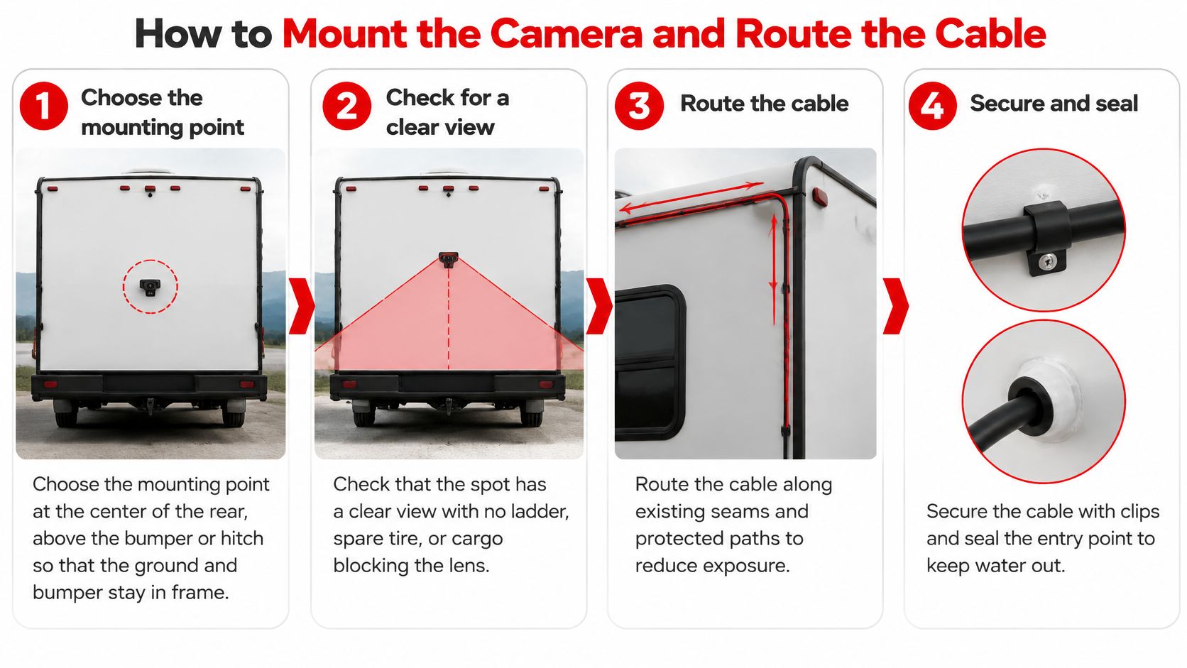
- Put the camera on the centerline, above the bumper or hitch, high enough to clear the ball and low enough that ground and bumper stay in frame. A cap-rail mount looks tidy and often aims over the zone you need.
- Swing the ladder, rear cargo doors, and hitch jack through their full travel. If a door skin kisses the lens at full open, move the bracket before you drill.
- Clean the panel to bare, sound surface and bed the bracket on a rubber gasket. The gasket kills vibration buzz and gives the sealant something to bite.
- Mark the entry, drill, and deburr. Fit a grommet. A sharp fiberglass edge will cut the jacket within a season, and a bare hole feeds rain straight into the wall.
- Seal the bracket and the entry with butyl or a neutral-cure silicone, and leave a drain path so water is not trapped behind the pad. Globbing sealant over a weep hole just builds a puddle.
- Clip the cable to the frame every 18 to 24 inches. Keep it at least 6 inches off exhaust components and clear of suspension, steps, and slide mechanisms. Existing seams beat a new hole through a wet bay.
- Leave a drip loop below the entry and a short service loop at the camera so you can unplug it without stressing the pins.
The usual miss is mounting too high or tilting the lens down until the distant ground disappears. Aiming comes after the mount is solid. For bracket styles and where each one fails on a coach tail, see this rear view camera mount guide.
Press the bracket by hand. It should not rock. Wipe the lens. Road film on day one means the seal and the aim were never checked.
A short install walk-through helps if you want to see clip spacing and the drip loop before you open a hole.
How to Wire the Camera and Connect the Monitor
Wrong colors are the fastest way to cook a camera. Brands do not share a palette, so the meter decides, not the diagram printed on a different kit.
- Disconnect the chassis battery, and the house battery if the circuit you are tapping is on the house side. A live probe in a crowded harness is how pins get bridged.
- Identify every lead with a multimeter. Confirm which wire is video, which is power, and which is ground before you crimp. A guess here can destroy the imager.
- Run video only on the shielded cable that came with the camera or monitor. An unshielded extension invites alternator whine and rolling bars.
- Land camera power on the fused source you already chose. Do not steal an unfused tap off a light socket.
- Pick up the reverse trigger from the reverse-lamp circuit. With the key on, that wire should read about 12 volts only in reverse and zero in park.
- Bond ground to clean bare metal on the chassis. Sand the paint, use a ring terminal and a star washer, and hit the joint with dielectric grease after it is tight. A screw into painted aluminum is not a ground.
- Mount the monitor where it does not cover the windshield or a mirror, and hide the lead in a loom so it cannot drop into the steering column.
How the monitor should behave
You have three honest display choices. A standalone monitor is simplest on an older coach with no video input. A mirror-mount display keeps the dash clear and works well if your factory mirror is already a wide block. A head-unit input looks factory, but only if that radio switches to camera video on the reverse trigger.
Set the default view to the rear camera, not a side camera you forgot to switch. Set linger time so the image stays up for a few seconds after you leave reverse. That pause is what lets you see the curb as you creep forward into a site. If you added side cameras, use split screen for slow maneuvering and a full rear image the moment the transmission hits reverse.
Photograph each crimp and keep a simple wiring sketch in the coach manual. You will want it the first time a connector corrodes. A clear backup camera wiring diagram is the reference to match against your own sketch, not a substitute for metering your harness.
Warranty coverage requires the product to be installed correctly and used for its intended purpose on the vehicle it was sold for. A camera jumpered to the wrong circuit, or fitted to a different coach than the one it was built for, is an install fault, not a failed part.
Aiming and Testing Coverage on a Large RV
Aim against marks on the ground, not against how wide the lens claims to be. NHTSA testing treats a 20-foot-long by 10-foot-wide zone directly behind the rear bumper as the field you should see, with the full width and height of test objects at positions A through E visible, and objects at the two closest positions showing at least 150 mm of their circumference. The three central targets should subtend an average visual angle of at least 5 minutes of arc, and no single central target should fall below 3 minutes.
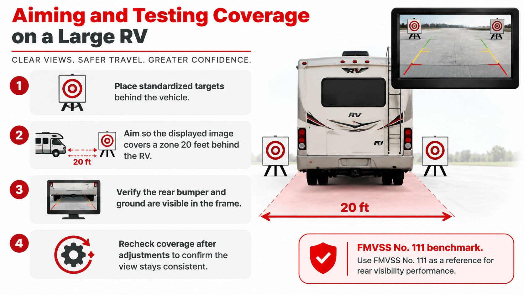
On a large coach, use that zone as a practical yardstick, not as a sticker you can claim. Many motorhomes were never built under the light-vehicle rear-visibility rule, so passing this drill does not certify the rig. It tells you whether the lens can show the space you are about to enter.
What has to be in the frame
- Low edge: You should see the bumper or the hitch, not a band of empty sky above it. If the bumper is missing, you cannot judge how close the ball is to a post.
- Upper edge: Rear corners or the loading area should still appear. A lens buried on the bumper lip hides the corners where site markers live.
- Loaded retest: Fill the water tank or hitch the usual toad and look again. Suspension compression changes camera pitch, and a view that worked empty can point at the bumper once you are heavy.
Mounting too high, or tipping the camera down to "see the hitch better," is how distant coverage disappears. A wide-angle lens makes this worse. Edges stretch, so a cone that looks far away on the monitor can be under the spare tire. If distance is hard to judge, narrow the aim or add a reference, such as a piece of tape on the ground at 5 feet and at 15 feet, and learn what those marks look like on your screen.
A commissioning drill before the first trip
Clean and center the lens. Confirm the image holds steady with the engine running, then repeat in daylight, low light, and rain or a hose spray. Set a child-height target, a cone or a bucket on a short stand, at the bumper and again farther back. From the seat, call out where it is before anyone moves the coach. Do it once more with a second person walking the blind side, and once with the trailer or bike rack you tow.
A camera that only looks right in an empty driveway has not been aimed.
Why a Camera Cannot Replace Mirrors or a Spotter
A clean monitor view of the empty pad behind your coach can still miss the bollard at the rear corner when the sun drops and the lens smears. A camera widens one slice of the world behind you, and only while someone is looking at it.
Rear-visibility systems became mandatory for nearly all new light vehicles under 10,000 pounds beginning May 1, 2018, after the National Highway Traffic Safety Administration tied the rule to backover crashes in driveways and parking areas, where it estimated an average of 210 fatalities a year. Normalizing the hardware did not normalize the habit.
NHTSA research found drivers glanced at the rear-visibility display during only 65% of backing maneuvers, so the system sat unused in roughly a third of them. A warning tone can pull attention late, after the bumper is already close. That late glance is not a scan of both corners, the hitch, and the ground beside the coach. Treat the screen as one more check, like a mirror, not as the check that lets you skip the others.
FMVSS No. 111 sets rear-visibility requirements for the systems it covers. It is a floor for the hardware, not a waiver that lets you drop mirrors from a coach that came with them. A flat screen compresses depth cues that a mirror gives at a glance, and it cannot cover the spotter's job of clearing the blind side.
A risk habit that survives a long coach
- Check both mirrors and the camera before the wheels roll in reverse. Glancing after you are moving is how the unused third of maneuvers happens.
- Use a spotter in a tight site, at the hitch, and any time a trailer is on the ball. Agree on one stop signal before you start.
- Treat rain, glare, a filthy lens, a bike rack, or a disconnected trailer as a blind-zone trigger. Stop and look with your eyes.
A camera widens the view and leaves the need to look, and a trained spotter, exactly where it was.
Troubleshoot Faults Before You Replace the Camera
You drop the coach into reverse and the screen stays black. Six of the seven faults in the table are a dead feed, a painted or high-resistance ground, a loose plug, or a bracket that walks itself loose. Replace the camera only after those checks fail.
FMVSS 111 conformity guidance treats field of view, image size, response time, deactivation, durability, default view, and linger time as part of a conforming system on vehicles at 10,000 pounds GVWR or less. Larger motorhomes still deserve that same pass bar: a stable image with the engine running, a usable view at night and in rain, no lag you have to wait on, tight connectors, and a picture that holds with the tow setup attached. A flaky image is a safety fault even when no sticker requires the camera.
| Symptom | Likely cause | First check | Fix |
|---|---|---|---|
| Black screen in reverse | Power or ground fault | Voltage at camera with engine running in reverse | Repair feed or ground, then retest |
| Rolling bars or flicker | Poor ground or voltage drop | Ground resistance and voltage under load | Clean and bond ground, upsize wire if needed |
| Image drops only while driving | Vibration at connector or loose bracket | Inspect bulkhead and bracket connections | Reseat, seal and secure the cable |
| Delayed or lagging image | Wireless interference or long analog run | Test with the monitor close to the camera | Move the receiver or switch to wired |
| Dim image when engine runs | Low charging voltage or shared load | Voltage at the monitor during charging | Give the camera a dedicated fused feed |
| Image fine but no switch-on in reverse | Reverse signal not live at camera or monitor | Meter on reverse circuit while shifting | Retap the reverse signal and confirm 12V in reverse |
| Fuzzy image after rain | Water inside lens or connector | Inspect lens and entry seal | Dry, reseal, replace the camera if fogging stays |
Watch what the picture does the moment the trailer plug seats. A screen that was clean on the coach alone starts rolling bars, or it goes black only with the 7-way mated. Corrosion in that plug, a cable that slaps the frame on rough roads, and water in the bulkhead connector track the same way: the fault follows the tow connection, not a random key cycle. I treat that pattern as a circuit or mount problem until the meter says otherwise.
A failed imager is the case where voltage at the camera is correct in reverse, the ground bond is solid, and the picture is still gone. The backup camera not working notes walk that same split between a bad camera and a bad circuit.
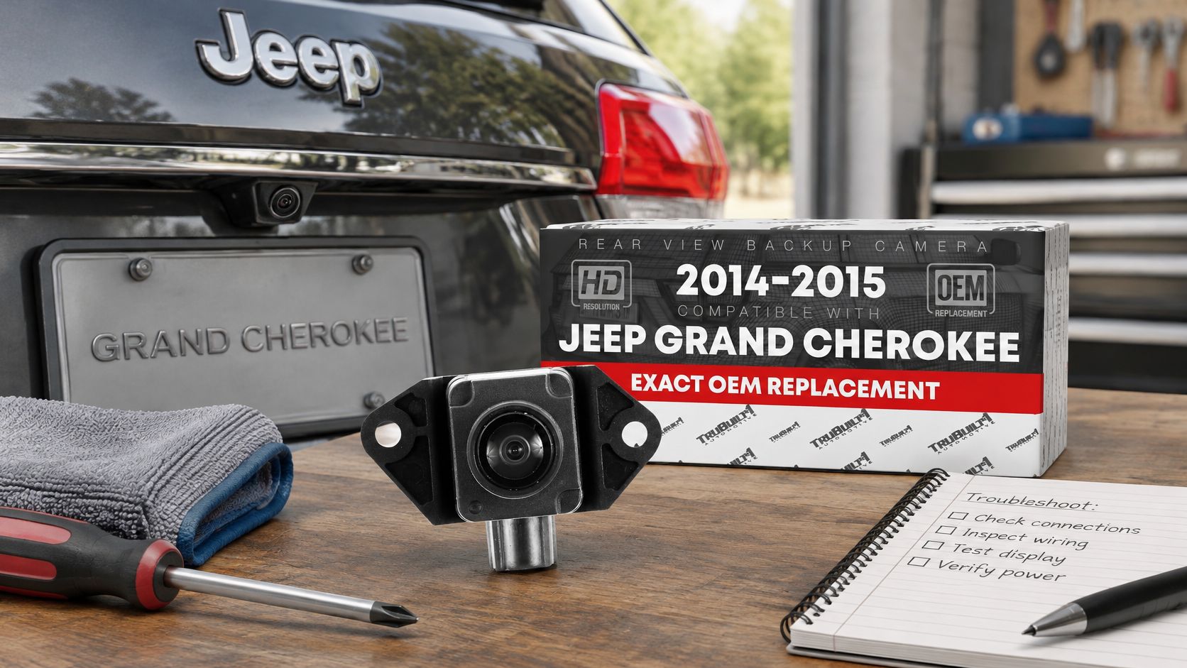
If the toad or a tow truck needs a camera of its own, match the original number instead of a lookalike housing. A Rear View Backup Camera for 2014-2015 Jeep Grand Cherokee lines up with OEM 68375333AA and the related 68137943-series numbers. That direct match is what you want once voltage, ground, and the part number all point at the failed camera.
T1A Auto offers CAPA certified rearview cameras. Use the vehicle search, or send year, make, model, and how the rig is set up so the parts team can confirm fit, before you pull the old one. When you are ready to order, visit T1A Auto.
